My Canon EOS 1100D Astro Mod: DIY for Deep Sky
Out with the Old, In with the New: Astro-Modding My Canon 1100D!
After selling my Baader-modified Canon 350D, I recently acquired a new DSLR: the Canon EOS 1100D. As soon as it arrived, it was time for a mod!  This camera offers several advantages over the slightly aging 350D:
- No more annoying amp glow from the internal amplifier in the bottom right of long-exposure images (check out the dark frames below).
- Noise is also much better managed on this model, thanks to the DIGIC 4 processor and 14-bit encoding instead of 12-bit (again, see the dark frames below).
- A single USB cable handles all camera functions, including Bulb mode. So long, serial port Bulb cable!
- LiveView mode is available (not super critical for my setup, but handy for mobile astrophotographers).
- A smaller pixel size: 5.2µm instead of 6.4µm. This is a big win for my specific situation because with my new setu, this pixel size gives me a sampling rate of 1.87”/pixel, down from 2.31”/pixel. The math says this is pretty much ideal for my current configuration!
Here’s the 10th dark frame from a series of 20 taken with the Canon 350D. 5-minute exposure at 800 ISO, temperature: 0ºC. Curves heavily stretched: 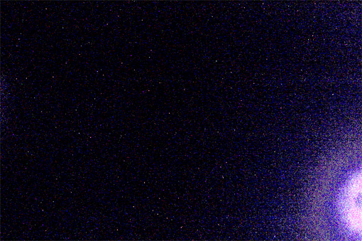 Photo taken under the exact same conditions, but with the Canon 1100D. Same stretching applied:
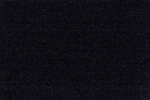
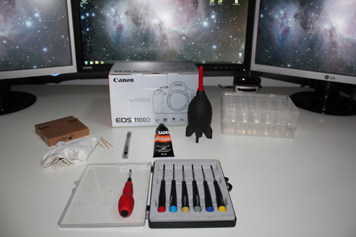
Unlike the 350D, modifying the 1100D doesn’t require any soldering. However, as we’ll see, that doesn’t necessarily make the operation any easier! First things first, here’s a non-exhaustive list of tools and materials to gather before diving into the modification:
- A good quality set of electronics screwdrivers.
- A few toothpicks
- A dust blower (or canned air)
- A compartment box to keep screws organized as you remove them
- A tube of strong adhesive, like “SADER Mirror” glue
- A utility knife with a fresh, thin blade
- An optical cleaning cloth (just in case)
- An Astrodon Inside filter or equivalent
- Several airtight containers (like Tupperware)
- Tweezers, or ideally, curved electronics pliers
 STEP 1: Start by sliding the viewfinder eyecup upwards. Store it safely in a box.
 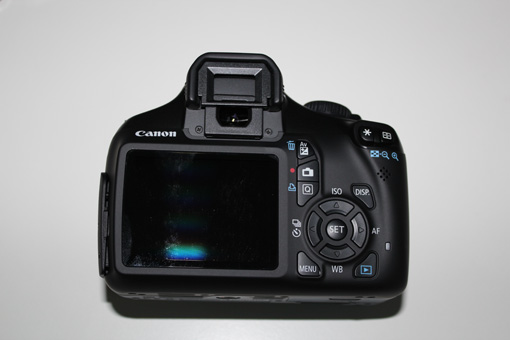 STEP 2: Next, unscrew the two short screws hidden underneath.
 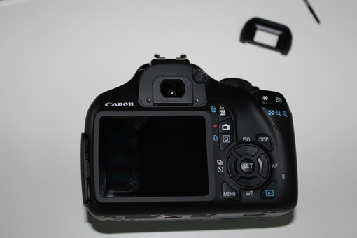 STEP 3: Now, flip the camera over.
  STEP 4: Unscrew the four screws on the bottom. The two in the middle are short, and the two on the ends are medium-length.
 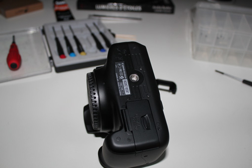 STEP 5: Move to the side with the connectors.
 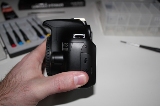 STEP 6: Remove the medium-length screw.
 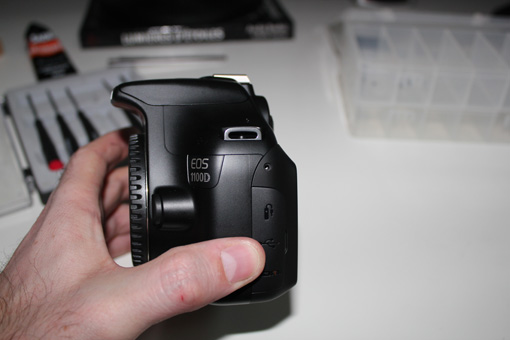 STEP 7: Now, head to the other side.
 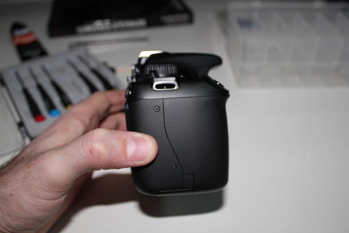 STEP 8: Remove the two screws. The top one is long, and the bottom one is medium-length.
 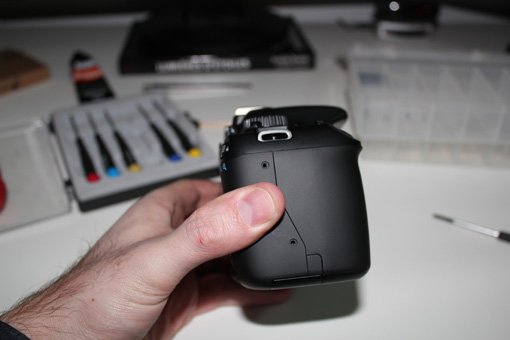 STEP 9: Move to the top.
 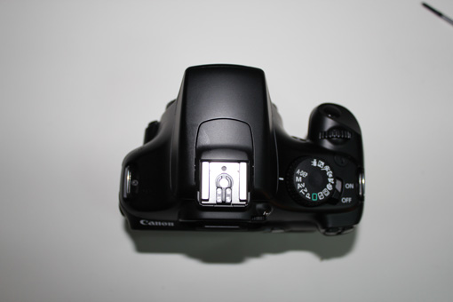 STEP 10: Remove the two screws located near the metal strap rings. The right one is long, and the left one is short.
 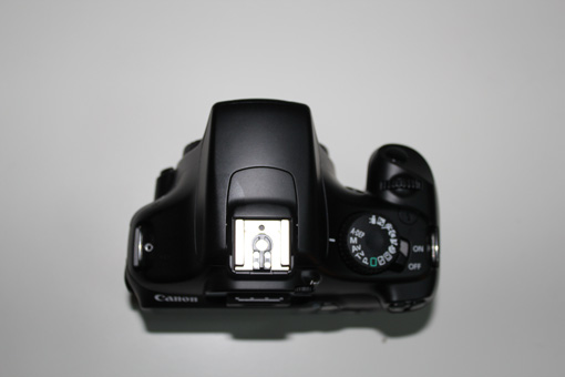 STEP 11: Next, remove the two medium-sized screws behind the connector cover.
 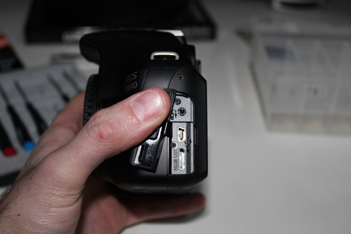 STEP 12: Now, gently pull the back of the camera to separate it from the front. Be careful not to pull too hard, as two ribbon cables (one orange, one blue) connect the back to the camera body.
 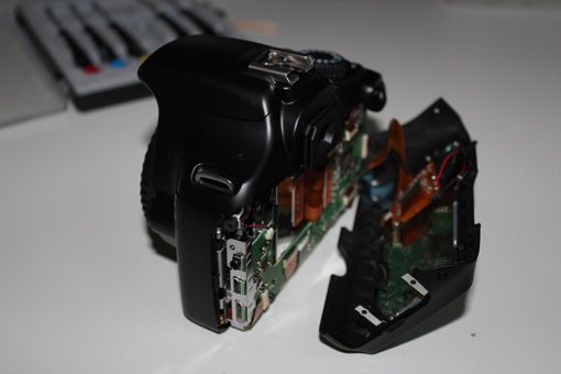 STEP 13: To disconnect these two ribbon cables, simply pry up the black retaining bars, then slide the cables out of their sockets.
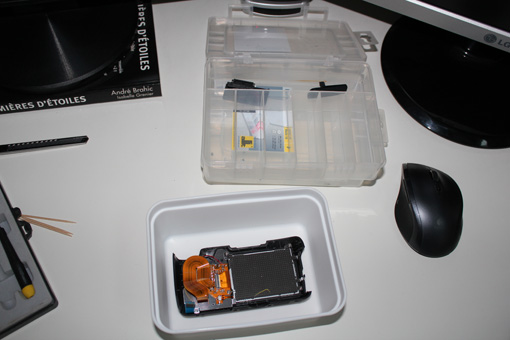
 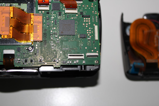 STEP 14: You can now set the back panel aside in an airtight container.
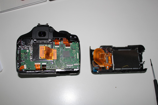
 STEP 15: Disconnect the 8 ribbon cables and the red and black wire.
 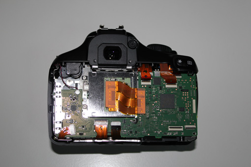 STEP 16: Pay attention: the middle ribbon cable is a bit special. You’ll need to gently pry it up with your fingernail.
 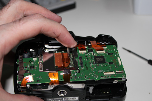 STEP 17: It’s time to unscrew the main circuit board. Just remove the 3 small screws and the two long ones as shown below.
 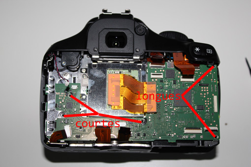 STEP 18: Remove the metal cover on the left by sliding it off. Pay close attention to how it’s mounted; this will make reassembly much easier!
 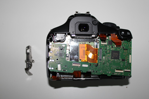 STEP 19: Carefully flip the board over. On the back, you’ll find a red and blue cable, as well as an optical fiber in a black sleeve. When you flip the board, this optical fiber should normally detach itself. If not, carefully remove it from its white connector. Also, disconnect the red and blue cable. For reassembly, use tweezers or, even better, curved electronics pliers to reconnect the optical fiber to its connector.
 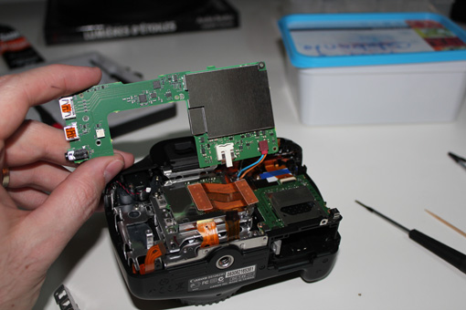 STEP 20: Store the main circuit board safely in an airtight container.
 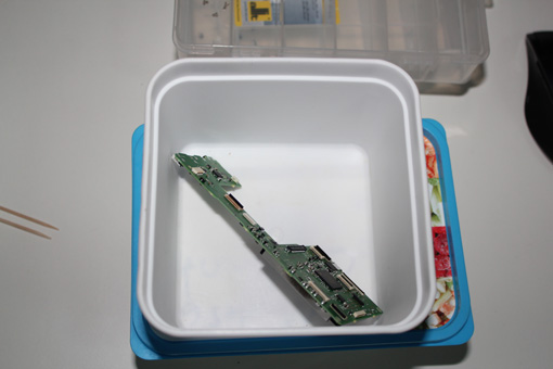 STEP 21: Unscrew the screw and remove the diopter adjustment wheel on top, next to the eyecup.
 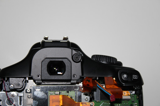 STEP 22: Set them aside.
 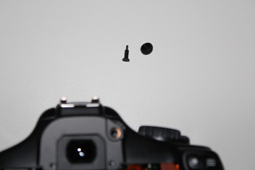 STEP 23: Now let’s move to the front of the camera. Remove the 3 long screws around the lens mount.
 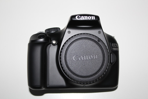 STEP 24: Flip the camera over and remove the remaining 2 screws. The one on the edge is medium-length, the other is long. While you’re at it, you can also remove the battery compartment door. Just gently pull it off.
 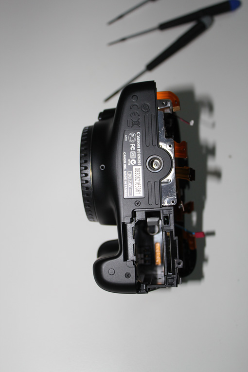 STEP 25: Now you need to remove the front panel. The easiest way is to gently pry it with a screwdriver near the tripod screw mount. The front panel should then slide off, almost by itself.
 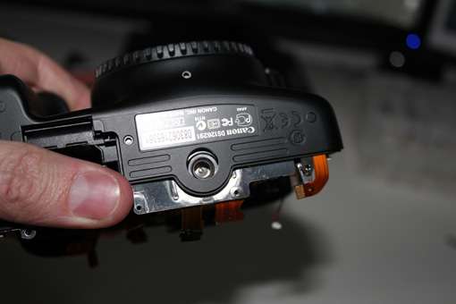 STEP 26: Set it aside.
 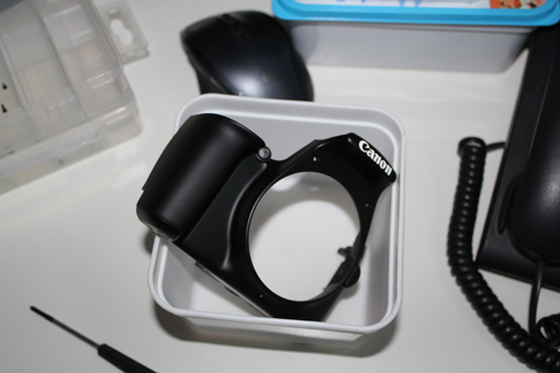 STEP 27: We’re already getting a much clearer view!!!
 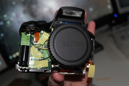 STEP 28: Slightly slide the top of the plastic shell without fully removing it, then unscrew the two short, flat-head screws. See their locations in the photo below.
 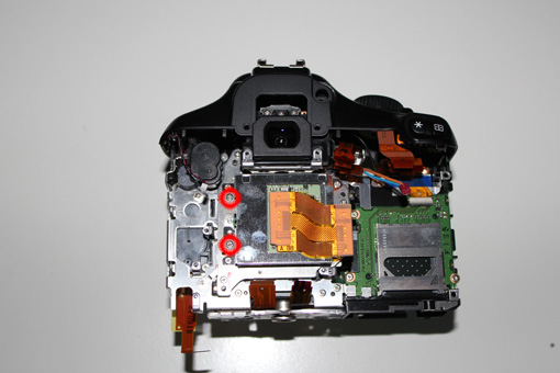 STEP 29: Next, unscrew the three long screws holding the CMOS sensor in place. See their locations in the photo below. Before attempting to remove it, be sure to read the next step carefully!
 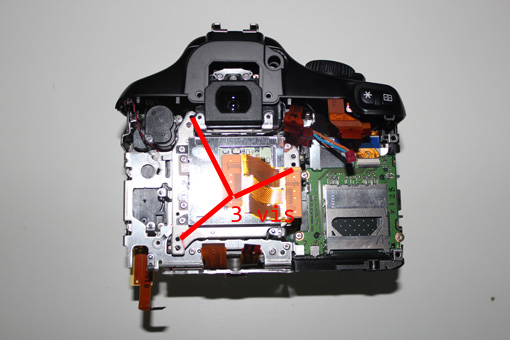 STEP 30: Caution! You’re about to remove the CMOS sensor from its housing. Take your time and avoid disturbing the small washers located under the 3 screws you just removed. Also, be careful not to touch the protective glass on the other side, as cleaning it will not be easy.
 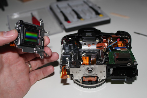 STEP 31: Place the camera body aside, protected from dust.
 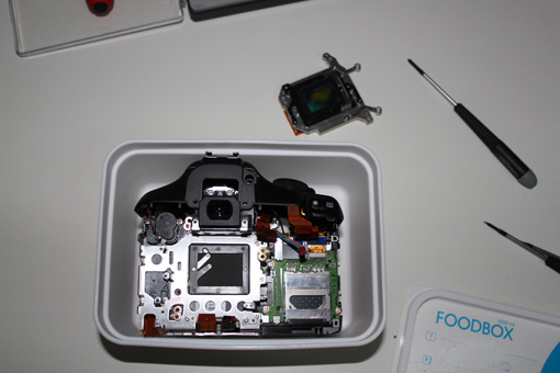 STEP 32: Let’s get serious! Now, remove the two small screws on the sensor side. Then, carefully separate the black plastic holder (which houses the two glass filters) from the metal bracket (which holds the CMOS sensor). This black plastic holder is attached to the metal part with very thin double-sided tape. The easiest way is to gently pry it with a utility knife, being careful not to go too deep and risk damaging the sensor.
 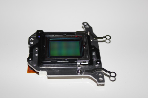 STEP 33: Once detached, store the CMOS sensor away from any dust.
 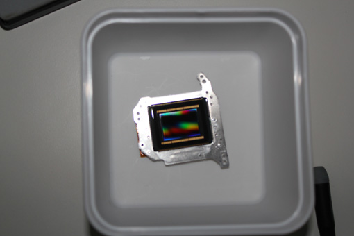 STEP 34: Next, you need to remove the small metal bar from the plastic holder. I find the easiest way is to gently pry it from the side with a very thin screwdriver.
 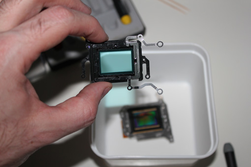 STEP 35: This is probably the most nerve-wracking part of the entire operation: removing the IR filter. It’s crucial to understand that you’re looking at two filters here! The first one, the IR filter, needs to be preserved. The second one, underneath, is the one we’re removing and replacing. So, to remove the IR filter without breaking it, you need to carefully detach it. It’s glued at the four midpoints, where the bulges and glue are clearly visible. I recommend running a very thin utility knife blade all around the filter, paying special attention to these glued bulges. Once pre-cut, you’ll need to very gently pry it up with tiny movements using a very thin screwdriver. The glass is only a few tenths of a millimeter thick, so you really need to proceed gradually. The first time I did this, I think I spent a good fifteen minutes carefully prying it off without any damage. TAKE YOUR TIME!
 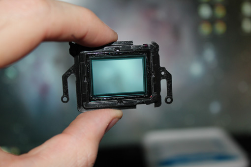 STEP 36: Alright, it’s done. The IR filter is removed and safely stored in a small, dust-free box. All that’s left is to remove the original filter and replace it with our new, astro-optimized filter!
 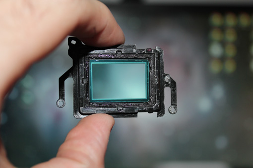 STEP 37: To do this, simply cut the seal all around with a very thin utility knife blade, then push from the other side with your thumb to pop it out. When I did this, a tiny piece broke off, but that’s okay. You’ll need to remove any remaining small pieces with the utility knife.
 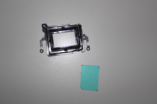 STEP 38: The final step before reassembly: replacing the filter with the astro filter and putting the IR filter back in place. Apply a tiny bit of glue in the four corners with a toothpick for precision, then carefully set the new filter in. Let the glue dry thoroughly and double-check that no traces appear on the filter. If needed, use a dust blower or, in the worst case, a clean optical cloth. Then, proceed similarly for gluing the IR filter back in. For this one, use the bulges as points to apply the glue. At every stage, it’s super important to make sure your filters are spotless!
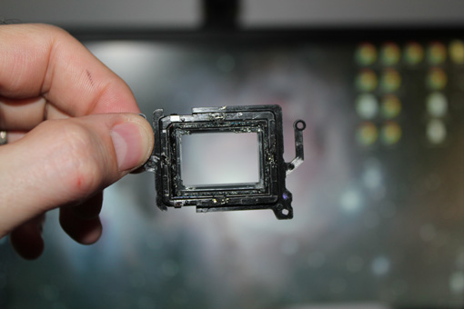
And there you have it! The disassembly and filter replacement are complete. Now, all you need to do is follow these tutorial steps in reverse order to reassemble your 1100D. Have fun! This operation isn’t complicated; you just need to take your time… This tutorial is unofficial, and the author cannot be held responsible for any potential damage to your camera!